UNOをスリープさせてみる
まずは以下を一通り読んでみる。
playground.arduino.cc
Forumの中のPlayGroundにある記事なのだが以下の4点を把握できる。
1、スリープにもいくつかモードがありIDOLはカウンターを停止させないとすぐにスリープ解除されてしまう
2、外部割り込みのPINは決まっている(2Pinor3Pin)
3、スリープ前にLED等は消灯(電力消費停止)しておかないとスリープしてもLEDは点灯したまま
4、スリープの仕方も複数あるらしく古いやり方もあってWEB上には混在している。
具体的には上記記事のサンプルを使ってみましょう
#include <avr/sleep.h>

/* Sleep Demo Serial
 * -----------------
 * Example code to demonstrate the sleep functions in an Arduino.
 *
 * use a resistor between RX and pin2. By default RX is pulled up to 5V
 * therefore, we can use a sequence of Serial data forcing RX to 0, what
 * will make pin2 go LOW activating INT0 external interrupt, bringing
 * the MCU back to life
 *
 * there is also a time counter that will put the MCU to sleep after 10 secs
 *
 * NOTE: when coming back from POWER-DOWN mode, it takes a bit
 *       until the system is functional at 100%!! (typically <1sec)
 *
 * Copyright (C) 2006 MacSimski 2006-12-30
 * Copyright (C) 2007 D. Cuartielles 2007-07-08 - Mexico DF
 *
 *  This program is free software: you can redistribute it and/or modify
 *  it under the terms of the GNU General Public License as published by
 *  the Free Software Foundation, either version 3 of the License, or
 *  (at your option) any later version.
 *
 *  This program is distributed in the hope that it will be useful,
 *  but WITHOUT ANY WARRANTY; without even the implied warranty of
 *  MERCHANTABILITY or FITNESS FOR A PARTICULAR PURPOSE.  See the
 *  GNU General Public License for more details.
 *
 *  You should have received a copy of the GNU General Public License
 *  along with this program.  If not, see <https://www.gnu.org/licenses/>.
 *
 */

int wakePin = 2;                 // pin used for waking up
int sleepStatus = 0;             // variable to store a request for sleep
int count = 0;                   // counter

void wakeUpNow()        // here the interrupt is handled after wakeup
{
  // execute code here after wake-up before returning to the loop() function
  // timers and code using timers (serial.print and more...) will not work here.
  // we don't really need to execute any special functions here, since we
  // just want the thing to wake up
}

void setup()
{
  pinMode(wakePin, INPUT);

  Serial.begin(9600);

  /* Now it is time to enable an interrupt. In the function call
   * attachInterrupt(A, B, C)
   * A   can be either 0 or 1 for interrupts on pin 2 or 3.
   *
   * B   Name of a function you want to execute while in interrupt A.
   *
   * C   Trigger mode of the interrupt pin. can be:
   *             LOW        a low level trigger
   *             CHANGE     a change in level trigger
   *             RISING     a rising edge of a level trigger
   *             FALLING    a falling edge of a level trigger
   *
   * In all but the IDLE sleep modes only LOW can be used.
   */

  attachInterrupt(0, wakeUpNow, LOW); // use interrupt 0 (pin 2) and run function
                                      // wakeUpNow when pin 2 gets LOW
}

void sleepNow()         // here we put the arduino to sleep
{
    /* Now is the time to set the sleep mode. In the Atmega8 datasheet
     * https://www.atmel.com/dyn/resources/prod_documents/doc2486.pdf on page 35
     * there is a list of sleep modes which explains which clocks and
     * wake up sources are available in which sleep mode.
     *
     * In the avr/sleep.h file, the call names of these sleep modes are to be found:
     *
     * The 5 different modes are:
     *     SLEEP_MODE_IDLE         -the least power savings
     *     SLEEP_MODE_ADC
     *     SLEEP_MODE_PWR_SAVE
     *     SLEEP_MODE_STANDBY
     *     SLEEP_MODE_PWR_DOWN     -the most power savings
     *
     * For now, we want as much power savings as possible, so we
     * choose the according
     * sleep mode: SLEEP_MODE_PWR_DOWN
     *
     */
    set_sleep_mode(SLEEP_MODE_PWR_DOWN);   // sleep mode is set here

    sleep_enable();          // enables the sleep bit in the mcucr register
                             // so sleep is possible. just a safety pin

    /* Now it is time to enable an interrupt. We do it here so an
     * accidentally pushed interrupt button doesn't interrupt
     * our running program. if you want to be able to run
     * interrupt code besides the sleep function, place it in
     * setup() for example.
     *
     * In the function call attachInterrupt(A, B, C)
     * A   can be either 0 or 1 for interrupts on pin 2 or 3.
     *
     * B   Name of a function you want to execute at interrupt for A.
     *
     * C   Trigger mode of the interrupt pin. can be:
     *             LOW        a low level triggers
     *             CHANGE     a change in level triggers
     *             RISING     a rising edge of a level triggers
     *             FALLING    a falling edge of a level triggers
     *
     * In all but the IDLE sleep modes only LOW can be used.
     */

    attachInterrupt(0,wakeUpNow, LOW); // use interrupt 0 (pin 2) and run function
                                       // wakeUpNow when pin 2 gets LOW

    sleep_mode();            // here the device is actually put to sleep!!
                             // THE PROGRAM CONTINUES FROM HERE AFTER WAKING UP

    sleep_disable();         // first thing after waking from sleep:
                             // disable sleep...
    detachInterrupt(0);      // disables interrupt 0 on pin 2 so the
                             // wakeUpNow code will not be executed
                             // during normal running time.

}

void loop()
{
  // display information about the counter
  Serial.print("Awake for ");
  Serial.print(count);
  Serial.println("sec");
  count++;
  delay(1000);                           // waits for a second

  // compute the serial input
  if (Serial.available()) {
    int val = Serial.read();
    if (val == 'S') {
      Serial.println("Serial: Entering Sleep mode");
      delay(100);     // this delay is needed, the sleep
                      //function will provoke a Serial error otherwise!!
      count = 0;
      sleepNow();     // sleep function called here
    }
    if (val == 'A') {
      Serial.println("Hola Caracola"); // classic dummy message
    }
  }

  // check if it should go to sleep because of time
  if (count >= 10) {
      Serial.println("Timer: Entering Sleep mode");
      delay(100);     // this delay is needed, the sleep
                      //function will provoke a Serial error otherwise!!
      count = 0;
      sleepNow();     // sleep function called here
  }
}
ESPr Developer 32でリモコンを作ってみる
GitHub - z3t0/Arduino-IRremote: Infrared remote library for Arduino: send and receive infrared signals with multiple protocols]github.com
↑Githubからライブラリをダウンロードして
/書類/Arduino/libraries
に解凍したフォルダを移動する。
(UNOの時に使ったオリジナルライブラリはESP32系はどうさ対象外で、フォーク版を公開してくれている方がいるのでそちらを使います。)
Pin4に赤外線LEDをつなげる(←ここ大切 )
Pin13にタクトスイッチ をつなげる
#include <IRremote.h>

int SwitchBUTTON_PIN = 13;  //タクトボタン
int SEND_PIN =4;      //赤外線発信LED PRO Mini = 4
//int SEND_PIN =3;      //赤外線発信LED UNO=3

IRsend irsend(SEND_PIN);


void setup()
{
  Serial.begin(115200);
  pinMode(SwitchBUTTON_PIN, INPUT_PULLUP);
}

int lastButtonState2;
void loop() {
  //////////////////////////////////////////////////////////
  // If button pressed, send the code.
  int buttonState2 = digitalRead(SwitchBUTTON_PIN);
  if (buttonState2 == LOW && lastButtonState2 == HIGH) {
    Serial.println("SwitchButton Pressed, sending");
    //2FD946B //丸ごとチャンネル
    //2FD807F //chanenl 1
    irsend.sendNEC(0x2fd946b, 0x20);
    delay(500); // Wait a bit between retransmissions
  }
  lastButtonState2 = buttonState2;
  //////////////////////////////////////////////////////////
}
ちなみに上記コードの2FD946B 丸ごとChは下CT-90475(REGZA純正リモコン)の左上にある
ボタンを意味しています。
互換リモコン買ったんですがこのボタンが実装されてなくてならば作ってしまえ!
ということでこの記事書いてます。
UNOでリモコンを作ってみる
GitHub - z3t0/Arduino-IRremote: Infrared remote library for Arduino: send and receive infrared signals with multiple protocols
↑Githubからライブラリをダウンロードして
/書類/Arduino/libraries
に解凍したフォルダを移動する。
Pin3に赤外線LEDをつなげる
Pin13にタクトスイッチ をつなげる
#include <IRremote.h>

int SwitchBUTTON_PIN = 13;  //タクトボタン

IRsend irsend;

void setup()
{
  Serial.begin(115200);
  pinMode(SwitchBUTTON_PIN, INPUT_PULLUP);
}

int lastButtonState2;
void loop() {
  //////////////////////////////////////////////////////////
  // If button pressed, send the code.
  int buttonState2 = digitalRead(SwitchBUTTON_PIN);
  if (buttonState2 == LOW && lastButtonState2 == HIGH) {
    Serial.println("SwitchButton Pressed, sending");
    //2FD946B //丸ごとチャンネル
    //2FD807F //chanenl 1
    irsend.sendNEC(0x2fd946b, 0x20);
    delay(500); // Wait a bit between retransmissions
  }
  lastButtonState2 = buttonState2;
  //////////////////////////////////////////////////////////
}
ちなみに上記コードの2FD946B 丸ごとChは下CT-90475(REGZA純正リモコン)の左上にある
ボタンを意味しています。
互換リモコン買ったんですがこのボタンが実装されてなくてならば作ってしまえ!
ということでこの記事書いてます。
ESPr® Developer 32 使ってみる その2
ESPr Developer32 のピンアサイン
trac.switch-science.com
Pull-UP,Pull-Downはデフォルトでピン毎に決まっているものがあるので表で確認
アナログ入力できるピンでanalogRead()した時の電圧が3Vくらいで、4096段階
↑UNOは5Vで1024段階
Arduino pro mini のピンアサイン
Documentsタブを開いてGraphics DetaSheetをみてね
Arduino Pro Mini 328 - 5V/16MHz - DEV-11113 - SparkFun Electronics

ATTiny85のピンアサイン
TtinyCore UniversalでATTiny85をクリックしてPINアサインを確認
github.com

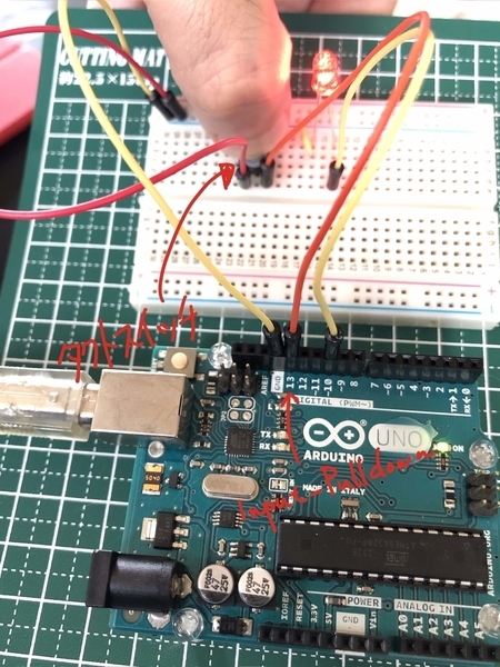
Input_PullDownでタクトスイッチ使ってみよう


#define switchiButtonPin 13
#define ledPin 10
int buttonState = 0;

void setup() {
  pinMode(ledPin, OUTPUT);
  pinMode(switchiButtonPin, INPUT_PULLUP); // Inputモードでプルアップ
}

void loop(){
  buttonState = digitalRead(buttonPin);
  if (buttonState == LOW) {     // ボタンが押されていたら、ピンの値はLOW
    digitalWrite(ledPin, HIGH);
  }
  else {
    digitalWrite(ledPin, LOW);
  }
  delay(50);

}
こちらを参考にさせていただきました。↓
novicengineering.com
Arduino Pro Mini 互換機 安いやつ買ってみた
www.shigezone.com
ShigeZoneさんでArduino Pro Miniの互換機買ってみました。
390円!!安い!!
ArduinoIDEからスケッチ書き出すのにはUSB-シリアル接続変換基板が必要なんだけど
手元になかったのとめんどくさかったので、UNOにつないでスケッチを書き込んでみました。
| Arduino Pro Mini | Uno | |
|---|---|---|
| GND | → | 接続しない |
| GND | → | GND |
| VCC | → | 3.3V |
| RXI | → | RX |
| TXO | → | TX |
| DTR | → | RESET |
UNOに空のスケッチをアップロードしておく。
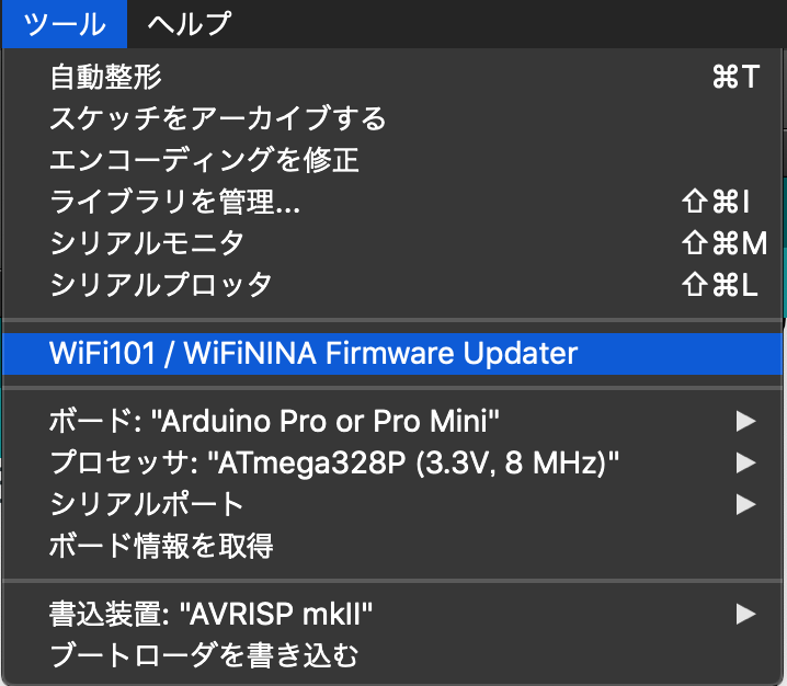
接続先のボードをArduino Pro Miniに変更して
プロセッサを変更してシリアル接続を確認(UNOで使っていたシリアルポートでOK)する。
Arduino Pro Miniにスケッチをアップロードする!!!
結構配線がごちゃごちゃするけどこれでできますね。
本来なら以下のような変換用のモジュールが必要なんだろうけどね〜
akizukidenshi.com
アマゾンでは↓こういうのかな
www.amazon.co.jp
ESPr® Developer 32 使ってみる その1

千石電子さん@秋葉原で
Wifi機能付きArduino互換機買ってきました。
なんで買ったかというと
1、夏に向けて部屋の温度と湿度を自動でロギングしたい
2、ロギングデータは自動でサーバーに送信してグラフにしたい
3、一定温度を上回ったらスマホに通知を送りたい
4、必要に応じてスマホからエアコンのオンオフ操作したい
猫がいるので外出中にうだってたらかわいそうなんで
昨今、ホーム家電が流行ってるんでちょっとやってみたいなぁ!「自力で!」
という軽い思いつきです。
実現するには
wifiにつながる道具で、phpが受け取れるようなプログラムかければできるんじゃね?
と思ってネットを調べてたら五百円程度でそれらしものができるというので調べてたら
ESP WROOM32ってモジュールでいけるらしいという事がわかりました。
さらにArduino互換らしいのでprogrammingも簡単そうだし
使いやすいボードがあればそれでいいかな?という軽い思いつきで秋葉原に行ってきました!
(ずーっと外出自粛してたので、そんなに遠くないし15分ほど電車に乗ってサッと買って帰ってきました)
Arduino UNOよりもめっちゃ小さくてまじか?って感じでしたが
早速適当にピンさしてハンダぽちぽちつけて
準備完了
「さ!Lチカでもすっかね!」
↓
「ん?シリアル接続できてねぇー!」
そうです、MacのUSBポートにつなげてもシリアルポートが表示されない
抜き差ししても、再起動してもダメ。
ネットで調べたてみたら
www.ftdichip.com
バーチャルCOMポートドライバーを入れろとのこと。
インストールしてみたけど、どうも挙動がおかしい
シリアル接続用の仮想COMポートが表示されるのは再起動した時に
USBケーブルを繋いでる時だけ・・・一度物理的に抜いたら再度刺しても認識されず。
なんでExtensionsフォルダから関係しそうなファイルを削除して
もう一度ドライバーをインストールし直したらうまくいきました。やった!
こいつらが怪しかったんで削除してみた。(自己責任でね)
SiLabsUSBDriver.kext
AppleUSBFTDI.kext
D2xxHelper.kext
FTDIKext.kext
Lチカは無事完了!
